Sunday, June 10, 2012

Attaching The Dome Motor Assembly To The Frame

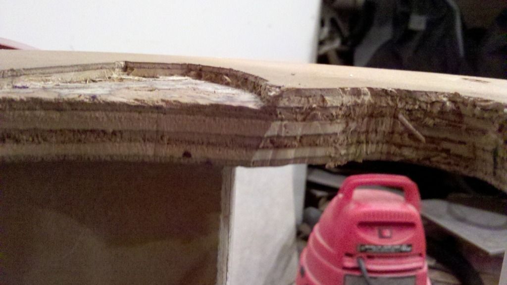
I decided it was time to attached the dome motor assembly to the top board of the frame. In order for the Rocker Bearing (the Lazy Susan used to rotate the dome) to spin freely, I had to chisel out a couple of areas for the assembly to in the frame.
In order to get the Rockler Bearing to turn, the wheel needs to make constant contact with the innermost portion of the bearing. To ensure continual contact, a spring is attached between two bolts. One on the top frame and one on the motor assembly swing arm.
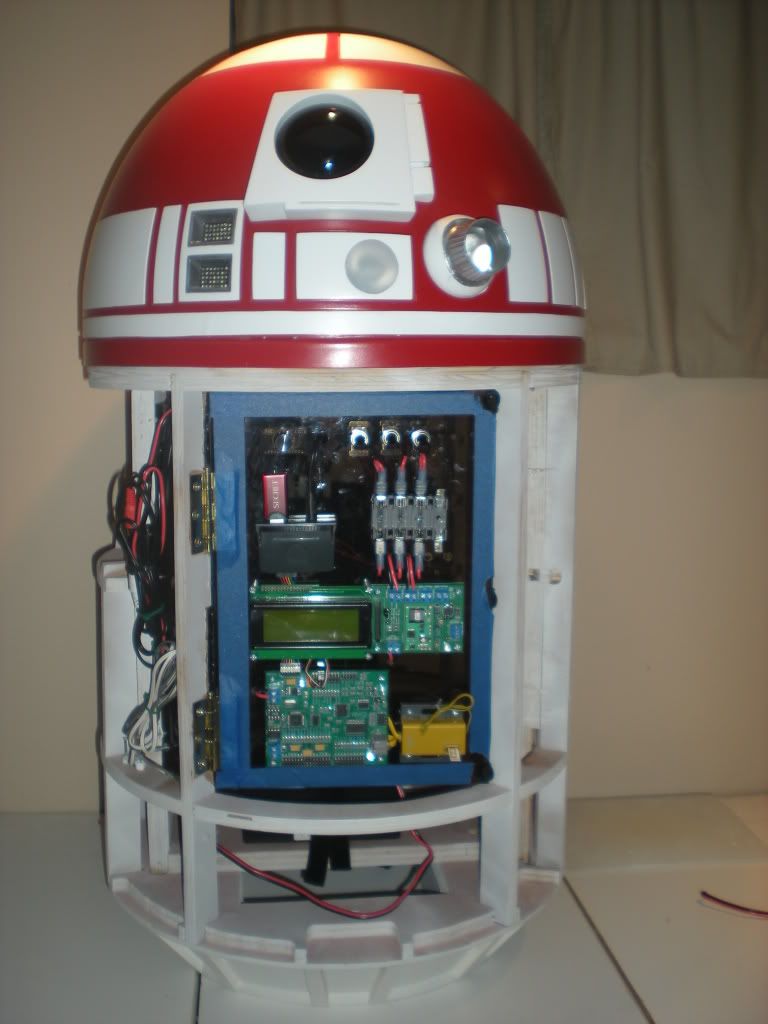
Once the spring is in place and all the bolts/screws are tightened R2-NU looked like the following.

Sunday, June 3, 2012

Dome Motor Assembly

I put together the dome motor assembly by attaching the copier motor I got from Clay Cardwell.

Tuesday, May 29, 2012

Shoulder Shims

I traced the shoulder horseshoes onto 1/8" styrene. These will be the shoulder shims. The shims will have to be smaller than the shoulders/legs and the horseshoes all around the perimeter by 1/8", and will be sandwiched between the shoulders/legs and the horseshoes to give the outer legs a bulkier look.

Friday, May 25, 2012

Outer Leg Painting/Sanding

I hung up R2-NU's outer legs on some string (running it through the shoulder holes) between some stakes in the yard about a week ago. I sprayed the legs several times (I lost count of how many) to give them an even look. Last night I wet sanded the legs with a piece of 220 grit sand paper to even out the surface and remove a few paint drips.
Hopefully, sooner than later, I will be able to put the final coats of paint on R2's legs.

Tuesday, January 10, 2012

Puttying The Outer Legs

With the wood glue dry, I puttied the gaps around the ankle pieces and the edges of the outer legs. I went a little overboard, but I figured I could sand everything down at once.

Friday, January 6, 2012

Outer Ankle Detail

I used a RotoZip with a Dremel bit to route out the outer ankle channel detail. I set the depth and routed out the majority of the channel. I then came back and used a razor blade to clean out the corner to make 90 degree angles. I then used a chop saw to cut down the outer ankle pieces to 4.1" and glued the ankle pieces to the legs.

Friday, October 21, 2011

Ankle Sanding/Painting

After the wood putty was dry, I sanded the ankle pieces smooth and painted them. I looks like they will need some more wood putty and need to be painted again later, but I can do that after I glue them to the legs.

Friday, October 14, 2011

Ankle Smoothing

After the flat part of the ankles were glued, I filled the gaps with wood putty to smooth them out.

Tuesday, October 11, 2011

Continuing The Ankle Fix

With the new angles cut on the ankle pieces, 6-year-old Joshua helped me trace the new end caps on some flat 1/4" plywood. He loves it anytime he can help! I cut them out and re-glued them.

Monday, October 10, 2011

Battery Box Hiccup

Clay and I continuted the work on the battery boxes by cutting the inside channel on three of the sets. We also continued work on the beefy ankle pieces. We realized we cut the angle at 35° rather than 55° so we had to cut a little more off. I will recut and reglue the flat portions this weekend so we are ready to cut out the channel pieces with the CNC next Monday.

Thursday, October 6, 2011

Starting Work On The Ankle Pieces

We had an off-schedule build night tonight. Clay and I worked on fixing the battery box sides now that the CNC has been re-leveled.

I bought an 8' long 6" diameter Tape-Ease Half Cylinder (the smallest amount I could purchase) and a 2'x2' sheet of 1/4" plywood from Lowe's to make outer and inner ankle pieces. We used club plans and Victor Franco's tutorial for this project. It took us awhile to figure out how to cut the half tubes with the equipment we had. We also ran into a little snag because part of the half cylinder was a little more flat than the other.

We ended up using a chop saw for all of the cutting. We cut three 4 1/8" length outer ankle pieces and three 4" length inner ankle pieces. The half cylinders have a height of 3". The outer ankle requires a cylinder height of 1 3/8" and the inner ankle requires a height of 1 1/4". We cut these pieces slightly bigger and used the sander to smooth out the edges and get them to the right height.

Once at the correct height, we angled the chop saw and cut a 55 degree angle off each ankle piece. We laid the slanted portion of the ankle piece on the flat 1/4" plywood, drew an over sized half circle, and then cut it out. The half circle was glued to the slanted portion of the ankle with plenty of overhang on each side. The over sized half circle will allow sanding later and still keep the needed angles while allowing the pieces to lay flat on the legs.

Sunday, July 17, 2011

Shoulder & Horseshoe Work

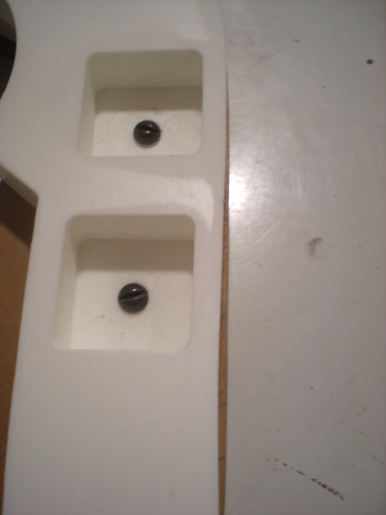
I took a long break from building and I got the bug today. I bought a couple of resin horseshoes from a club offering and realized that my shoulders needed to be trimmed in some places and built up in others. I started by sanding the back of the horseshoes and drilling out the mounting holes.


I used some spare screws I had lying around to mount the horseshoes to the legs. The newly mounted horseshoes will act as a guide for the router.


The wheel on the router bit roles along the horseshoe and cuts the wood underneath. The bit isn't long enough to cut the entire with of the leg, so the horseshoe was removed and the newly cut leg shoulder served as a guide to route out the rest of the leg.


I couldn't help but get a couple of nicks and scratches, so I'm using Bondo to fill the holes and make the legs smooth for painting.


My plan is to run the wires for the legs through the center support bar, so I drilled a hole in the center mounting bracket and ground down the sharp edges with the Dremel.

Sunday, June 12, 2011

Contagion Outbreak: 2011

I had a really good time, and I'm looking forward to going next year!

Friday, June 10, 2011

Making The Dome Motor Connection

While I was at Contagion, I mentioned to Clay that I wanted to hookup my dome motor working but I never got around to it because of electrical issues. I pulled out the documentation and found that the dome motor runs off of servo pin set four. And once again, we had to jumper power to the servo bank again. After Contagion I will make this look better!

Thursday, June 9, 2011

Slip Ring Connection Board Problems

I could not get a signal sent from the J.E.D.I. Controller Board through the Slip Ring and into the dome. Clay Cardwell came over to help me figure out the problem I was having. It turns out that my signal was getting through the Slip Ring Connection Boards and Slip Ring, but the power was not getting to the servo wire connection. I had to jumper the power inside the dome from the one of the main power terminals to provide power to one of the servo connection power terminals. Thank you for your help Clay!

Monday, June 6, 2011

Installed Sound System

With the electronics panel installed I turned my attention to the sound system. I installed a small Plexiglas panel on the inside back of R2 next to the hinge side of the previously installed electronics panel. This panel has the speaker amplifier and the unidirectional noise isolator installed on it.


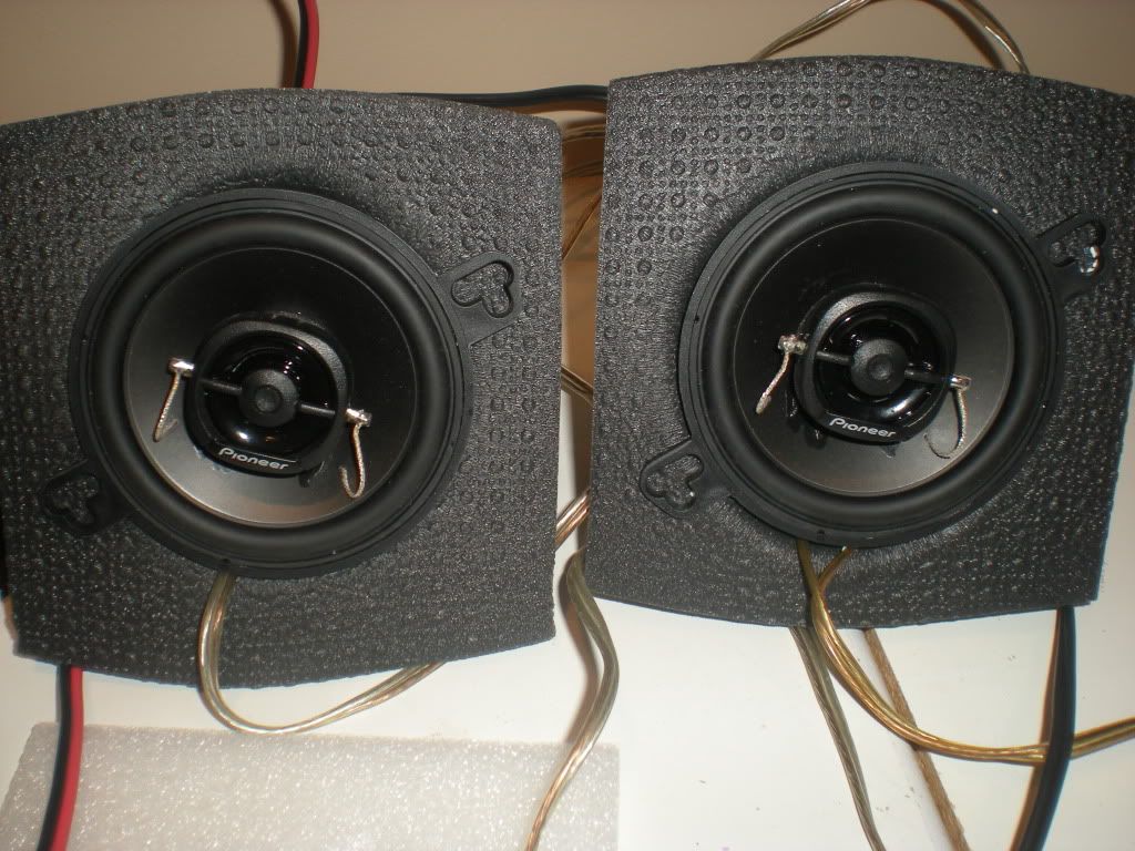
I temporarily attached the speakers to the inside front of R2-NU's body (behind where the center vents will be). Once the center vents are installed, I will have to remove the speakers and add spacers to move them away from the frame. I tacked the speaker wires to the frame next to the speakers and ran them on the outside of the up/down frame base to keep them away from any interior mechanisms that will be added later. I put baffles on the back of the speakers to redirect the sound.


I can't help but get excited about how R2-NU is coming together!

Tuesday, May 31, 2011

Electronics Moved To The Body

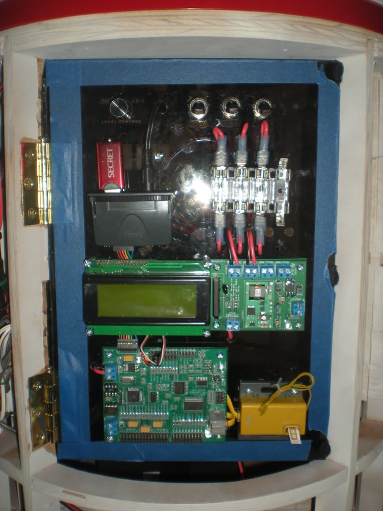
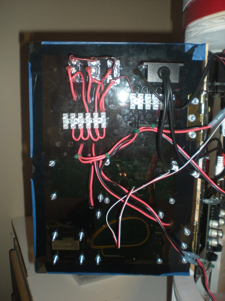
I started moving the electronics to the body a couple of days ago. I laid everything out on the Plexiglas and marked their positions. I then took a roll of tubing I bought from Lowes and cut them into 1/4" pieces for standoffs between the components and the Plexiglas door. The Plexiglas can be brittle at times, so I drilled each hole with a small bit and swapped out the bits for larger sizes until I got every hole the size I needed. I picked up a fuse panel from Radio Shack and installed it so that a 7 Amp fuse is on the main power switch to the left and two 2 Amp fuses run the J.E.D.I. Control system and sound amplifier. I put blue painters tape around the outside of the electronics panel door to mark off the area the outer skin door will need to open and close.

Thursday, May 19, 2011

Electronics Panel Started

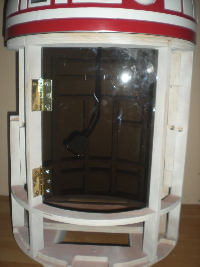
In my continuing attempts to divide the electronics between the dome and the body, I started installing an electronics panel. for my first attempt, I decided to use a piece of Lexan I had lying around. I cut it slightly larger than the back opening. I then picked up some cheap hinges with removable pins so I could pull the entire panel out of the body to work on it. I still need to chisel out the area where the hinges attach to the frame on the left side and install some type of latch or magnet on the right side. Once that is done, I can pull the panel off and start adding the Electronic components to it.

Tuesday, May 17, 2011

Sound System Test

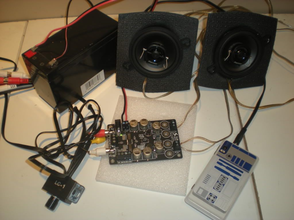
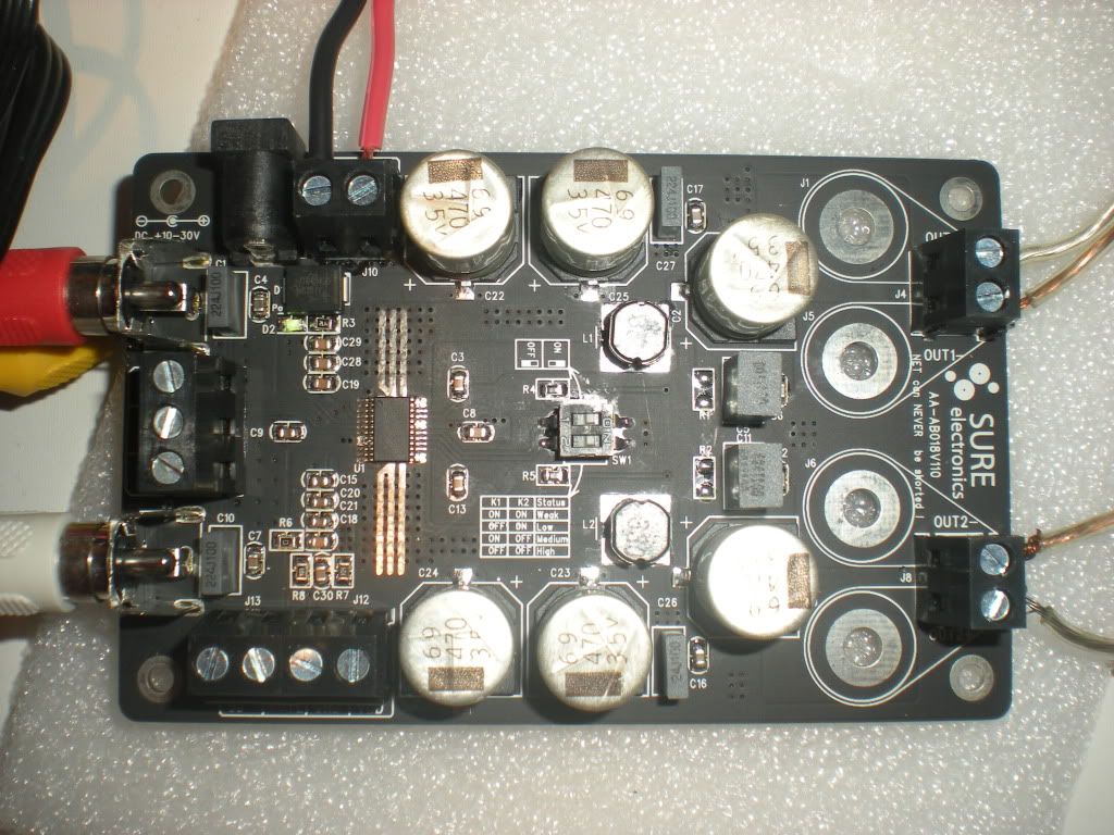
After DemiCon I decided I had to get my sound system working because nobody could hear R2 with the cheap test speakers I had. I've been looking for some time for an amplifier and speaker combo that would work in R2-NU. I ran across a post by Paul Bussiere describing some new sound equipment; and after doing research I bought what I needed from Parts-Express.com. There are several posts on Astromech.net talking about how the VMusic2 system has a hard time dealing with feedback and noise, so I purchased a PAC SNI1 Noise Isolator. I did not hook it up because I didn't have the right connectors, so I used my phone for testing rather than R2-NU's electronics.


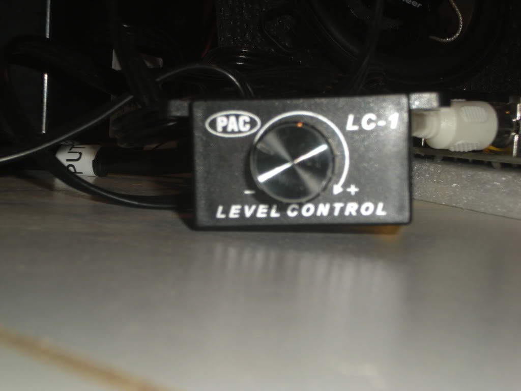
The amplifier does not have a potentiometer so I purchased a PAC LC1 Remote Amplifier Level Controller to handle the volume control.


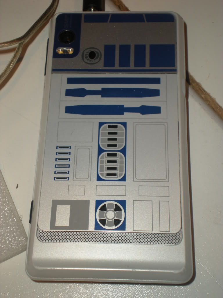
My phone providing music for testing.