Tuesday, April 21, 2009

Filling The Outer Leg Gap

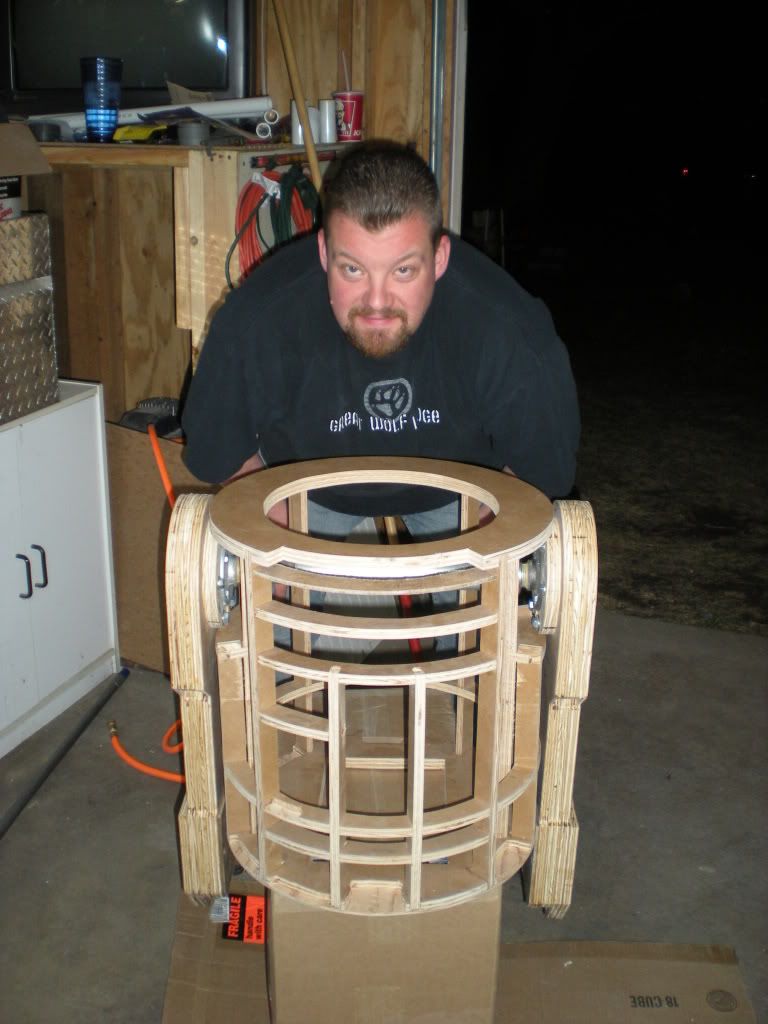
Outside of Dash, I'm the only one in our club that currently has plans to make his droid a 2-3-2 (an R2 that transitions from two legs, to three legs, and back to two legs); so I had to devise a way to keep the outer legs 1/2" away from the R2's body while still allowing the legs to rotate. I decided to use two pieces of 1/8" in HDPE plastic (self lubricating) in the shoulders rather than using a bearing and fill the gap between the shoulders and the two pieces of HDPE with wood that is the needed thickness.


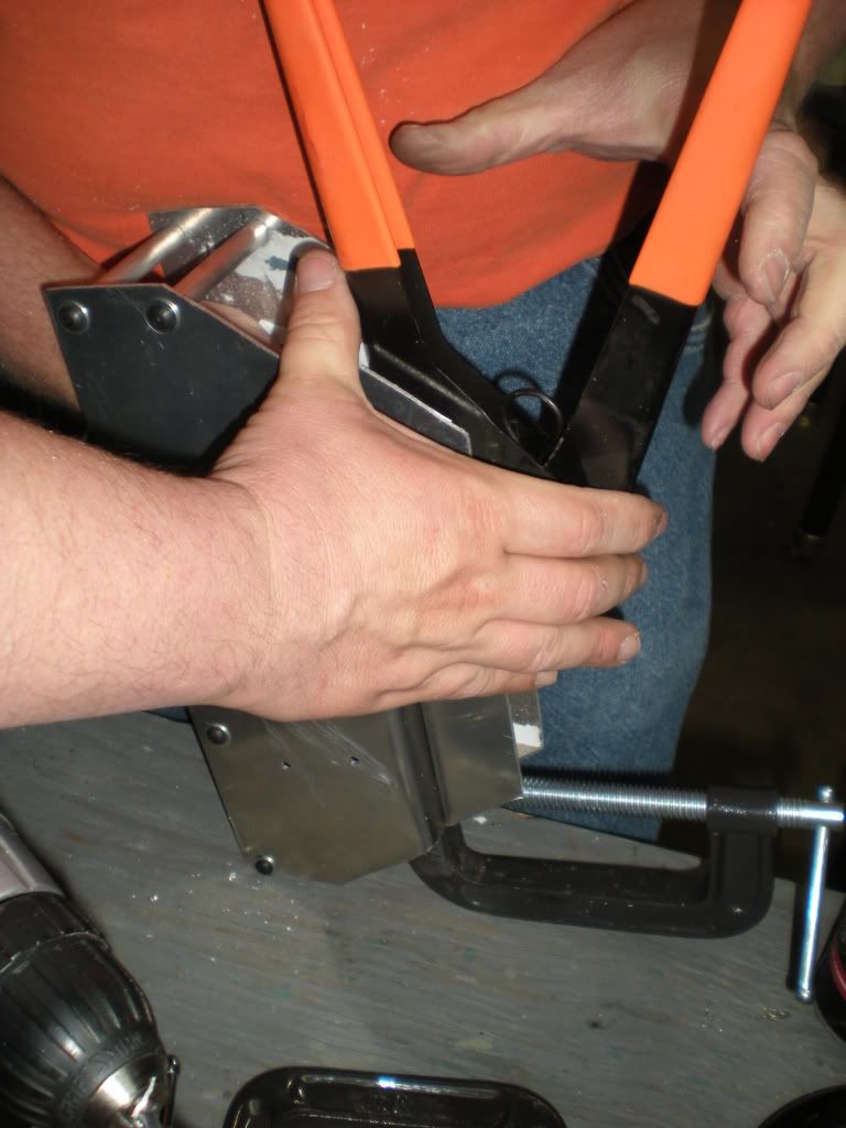
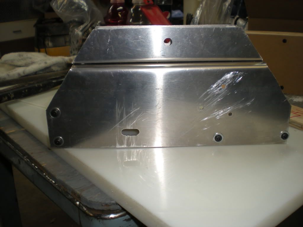
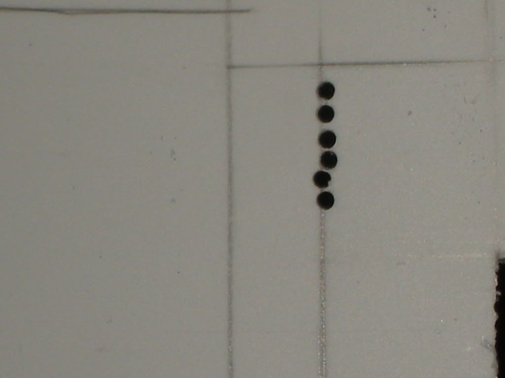
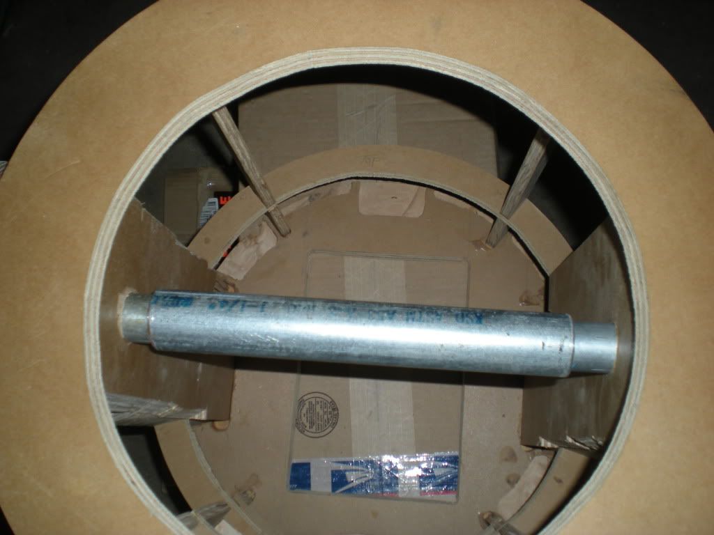
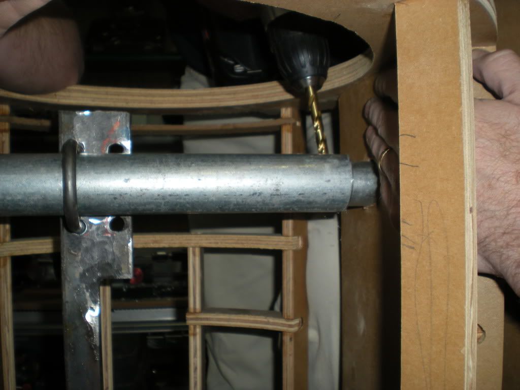
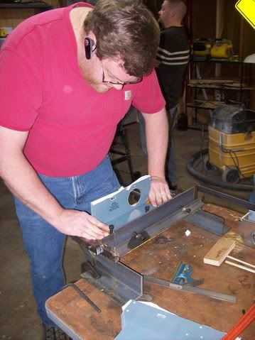
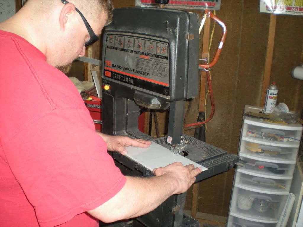
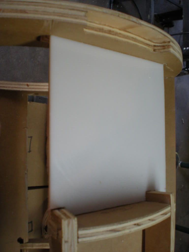
Cutting the 1/8" HDPE to attach flush to each side of the frame uprights.


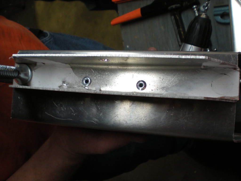
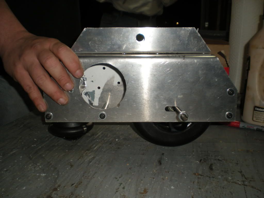
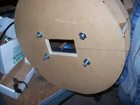
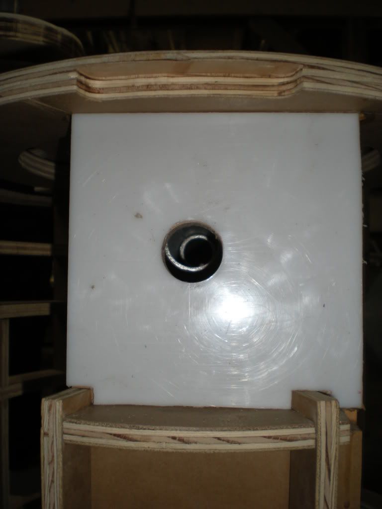
Drilled a 1 3/8" hole in the HDPE from the inside of the frame to make sure it was centered.


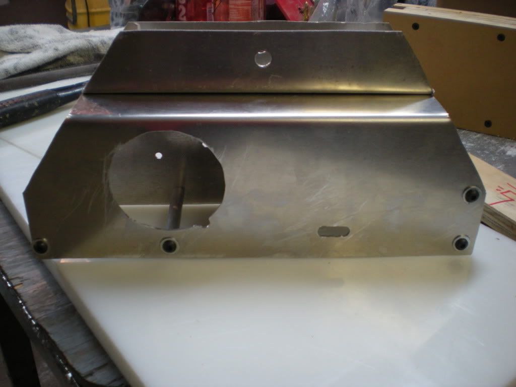
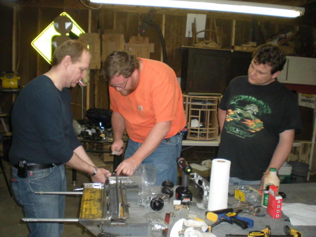
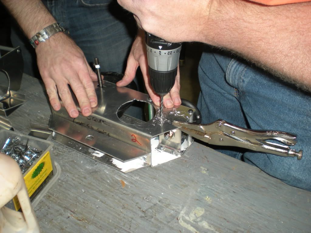
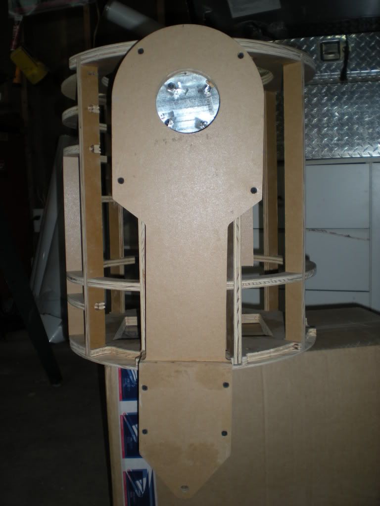
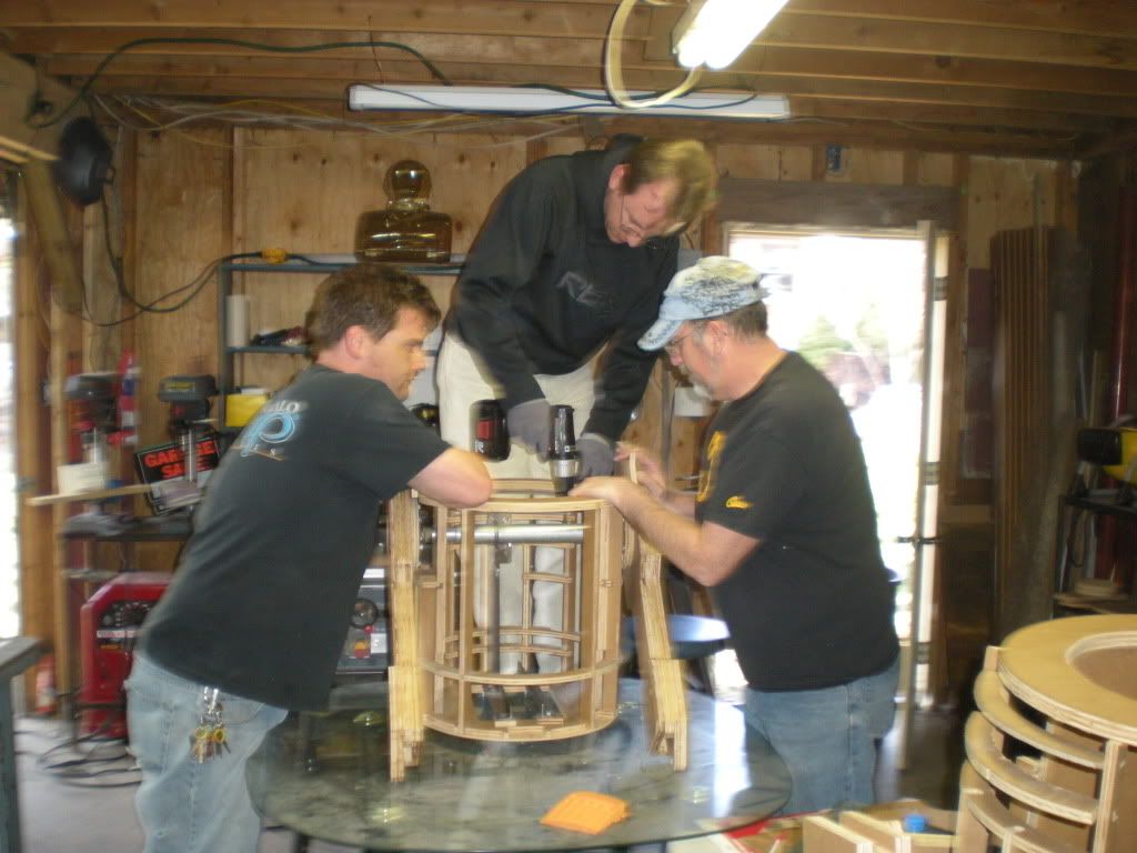
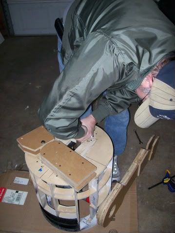
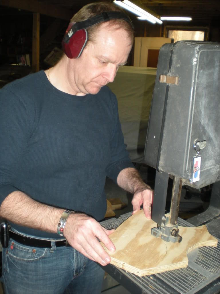
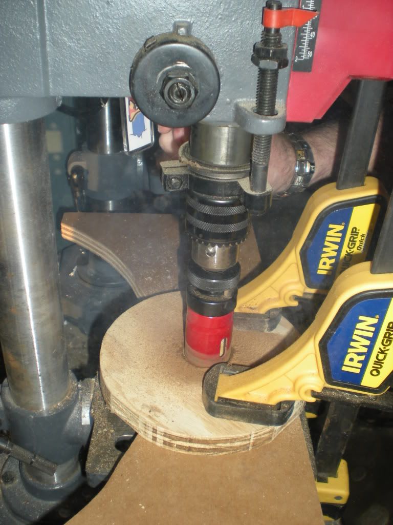
I drew extra circles the correct size on some 3/4" plywood, Clay helped me cut them out on the band saw, and we took turns using the hole saw to cut the center out of the shoulder spacer wood. When these pieces are finished, they will have one side routed/drilled out so it covers the leg bracket and hex bolt heads and sits flush against the existing 3/4" wood attached to the outer legs.


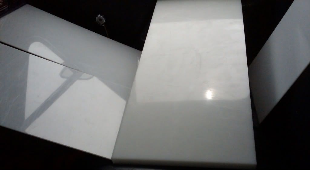
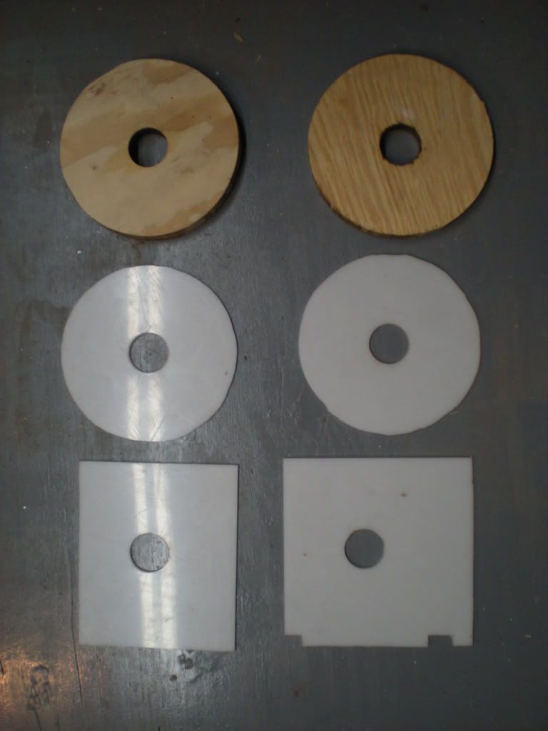
All the cut shoulder pieces so far.


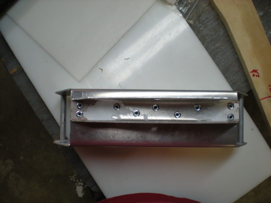
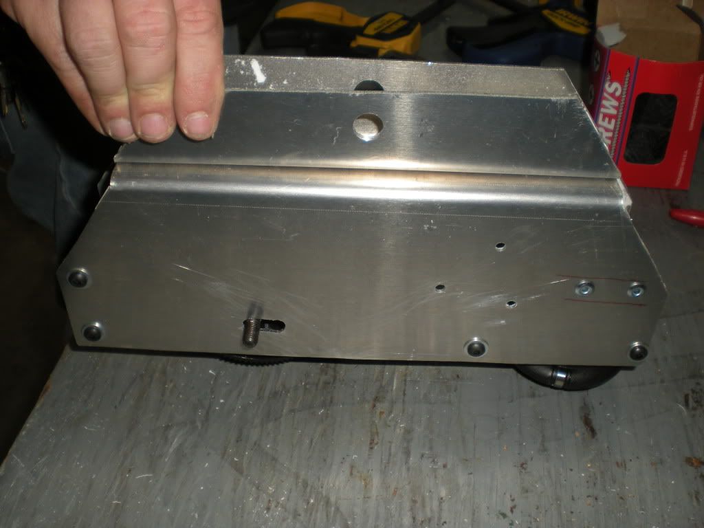
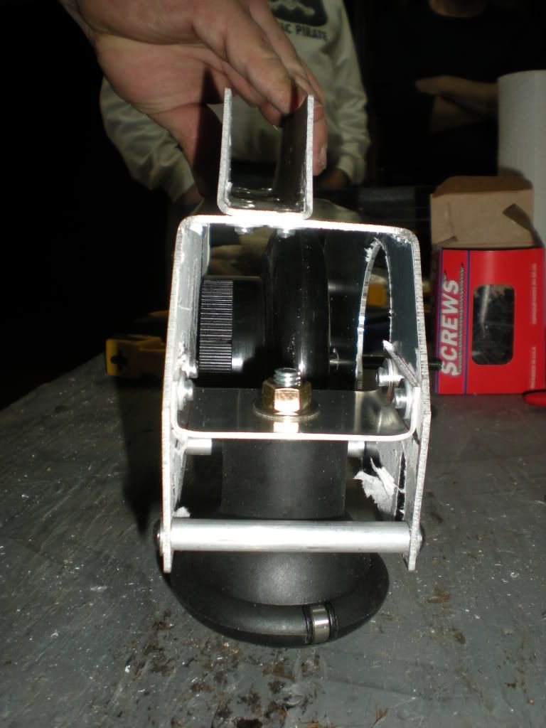
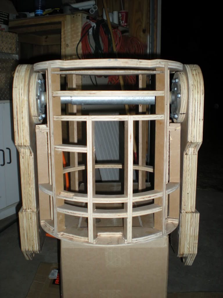
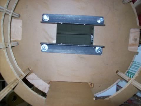
This is how the pieces will sit on the shoulder. I still have to add another filler piece, but I'm going to wait until I get this 3/4" plywood routed/drilled to hide the shoulder hardware.


Bushings Added

Steve brought the bushings we bulk ordered, so Moose and I installed them in the outer and center legs of our droids.

Motor Mount Meets Ankle

Steve got the bulk shipment of sleeve bushing, bearings, spacers, pop rivets, screws, and washers earlier today, so the group met to continue our work on the motor mount/ankles. Rather than use screws, washers, and nuts, the group decided to use 3/16" pop rivets and washers to attach the ankle aluminum to the motor mount aluminum.


We installed the motor and wheel to make sure there would still be enough clearance after the pop rivets where installed.


The ankle u-channel is offset on the motor mount, so the crew measured the distance using Moose's A&A motor mounts and JAG's foot shells to get the exact measurement.


The motor mount and ankle pieces where held in place by c-clamps and vice grips while the holes were drilled and the pop rivets installed.


After two pop rivets were installed, the spacing was checked again.


Okay, maybe we got a little crazy with the pop rivets; but this thing is solid.


With a couple of ankle pieces attached to their motor mounts, internal u-brackets where cut and bent to hold the omniballs. Getting the bends right on these pieces seemed more like an art than a science, but the end product looked pretty good. A hole was drilled in the bracket for the omniball and then the crew held it in place with vice grips while they drilled holes in the side of the motor mount and through the sides of the bracket. The bracket was held in place by using the same pop rivets used to attach the ankle to the motor mount.

Sunday, April 19, 2009

Dome Cutting

I started cutting my dome tonight. Clay suggested I use a Dremel to start the cut and finish off with a jigsaw at it's lowest speed. I didn't have access to a Dremel so I decided to use a drill with the smallest drill bit I could find. I drilled a series of pilot holes in a line big enough for the saw blade to fit. I then used a razor blade to cut the styrene pieces between the holes so the saw blade would fit. I was worried about breaking the styrene when I cutting so I decided to use a hand saw. The worst part of this method was it was loud and it drove my brother's dog nuts. It was a slow process and I had to do it by myself because the dog left the room. I was pretty happy with the results, and it will look even better when I sand the edges a little.

Tuesday, April 14, 2009

Outer Leg Holes

With everyone else getting their R2s up on legs, I had to drill holes in R2-NU's frame for his legs. Everyone was using a 1 3/8" hole saw to cut the hole for the legs to pass through the frame wall, but they noted that the hole was a little big and there was a little play between the leg pipe and the wood. Moose noticed that even though the hole saw size matched the diameter of the pipe, the hole saw had some teeth that flared out making the hole a little bigger than we wanted. Moose put the 1 3/8" hole saw bit in the drill press, turned it on at a very low speed, and used a file to file off the outward angled teeth. GOOD THINKING MOOSE! This worked great...nice fit. After the holes were drilled, I dry fit the legs and started taking pictures.

Spacers And Ankles Finished

Steve setup the metal lathe and I finished drilling and tapping the remaining spacers. Steve used the bending brake I got from Harbor Freight to bend the ankle pieces.


After I finished the spacers, Clay and Jason assembled the the rest of the motor mounts. The next time we meet, we will have to cut the offsets for the motors and attach the ankles to the motor mounts.

Jason's Leg Connections

Jason is building a static three leg R2, so he welded L brackets and used large hex bolts to hold the center foot in place. The center leg brackets have an upright bar with a muffler clamp on the end of it that clamps onto the pipe that connects the two outer legs and prevents them from moving. After the pipe is clamped, holes were drilled in each end of the pipes (the smaller ones attached to the outer legs and the larger ones) to hold the outer legs in place and at the correct angle.


J.E.D.I. Display Logics

After a year of researching, I finally pulled the trigger and ordered the J.E.D.I. (Joystick Enhanced Device Input) Control System Display Logics. My display logics purchase are kits for the +5V DC/DC Converter, two Front Logic Displays (FLD), one Rear Logic Display (RLD), three Holo Projector lights (HP), two Process State Indicators (PSI), one Display Controller, and nine 14" Extension Cables (for connecting components). This whole setup cost $235.75 (including shipping). I have to admit, all these parts seem a little intimidating; but I'm sure I can find a wealth of people willing to help me put these kits together.

Thursday, April 9, 2009

Leg Plastic

With everyone in the group getting their droids up on legs, I decided I better get moving with mine too. Because I intend to do 2-3-2 for my R2 rather than a static 3 leg, I need to plan for how the legs are going to move. The outer legs have to rotate and the center leg needs to move up and down without excessive friction. I decided to use the self lubricating HDPE from Midwest Plastics Inc. in varying sizes to allow the legs to move freely. For $32.10 I was able to get one 3/4"x11"x27" piece and three 1/8"x12"x18" pieces of HDPE.

Tuesday, April 7, 2009

Final Motor Bends

Steve and I worked on the motor mounts tonight. I used Steve's metal lathe to add threads to all the spacers we drilled at our last build night.


While I threaded all the spacers, Steve finished bending the motor mounts. The brake is a little too big for the ankle pieces, so he took it home to see if he could make some modifications and allow for more shallow bends. The group discussed ankle to motor mount connection options. Dan Baker used nuts and bolds, but we decide to use pop rivets.


Once all the bending and threading was done Steve, Jason, and I assembled six and a half motor mounts (that is all we could do until we drill out some more spacers).

Stationary Center Leg

A couple builders, Brad, and Jason all worked on the mounting of their center legs tonight while Steve and I worked on the motor mounts. Jason started everyone off by drilling out holes in his frame for the outer leg pipes. Later in the evening he cut his center leg brackets to size, welded some of it together, removed some of the slag with the ax and grinded off the rest.


Brad finished centering his center leg support and welded another small support angle iron piece to the top of the uprights to make it a little more rigid.

>

Moose decided to do something a little different with his second droid "Ed". He used a smaller hole for the center leg and a single upright piece of angle iron to attach to the pipe connecting the outer legs.